Barroso Rosa Sergio1*, Viera-Artiles, Jaime2, Valdiande-Gutiérrez José Julian3, Grant Andrea4
1University of Las Palmas de Gran Canaria, Medical and Surgical Sciences Department, Las Palmas de Gran Canaria, Spain and The Orthopaedic Research Institute of Queensland, Townsville, Australia
2ENT department, Hospital Universitario Marqués de Valdecilla, Santander, Spain
3Photonics Engineering Group, University of Cantabria, Santander, Spain
4The Orthopaedic Research Institute of Queensland, Townsville, Australia
*Corresponding Author: Barroso Rosa Sergio, University of Las Palmas de Gran Canaria, Medical and Surgical Sciences Department, Las Palmas de Gran Canaria, Spain and The Orthopaedic Research Institute of Queensland, Townsville, Australia; Email: [email protected]
Published Date: 13-11-2021
Copyright© 2021 by Sergio BR, et al. All rights reserved. This is an open access article distributed under the terms of the Creative Commons Attribution License, which permits unrestricted use, distribution, and reproduction in any medium, provided the original author and source are credited.
Abstract
Objective: This experimental study intends to test a novel device for preventing unintentional camera rotation during arthroscopic knee procedures.
Methods: The system consists on a multi-axis gyroscopic sensor that can be universally attached to any camera model in the market. A preliminary experience was designed to evaluate the operability of the device during actual arthroscopic meniscectomies.
Results: The system provided accurate real-time insight about camera orientation in relation to a selected working plane. The system is more useful when used within the tibio-femoral space and in the anterior (suprapatellar) compartment.
Conclusion: This device is able to assist orthopedics trainees and novel surgeons during arthroscopic training, reducing undesired camera rotation, disorientation, fatigue and surgical times.
Keywords
Arthroscopy; Training; Camera; Knee
Introduction
Arthroscopy has exponentially developed as one of the most utilized techniques in the field of orthopaedics in recent decades. The number of interventions carried out under this surgical modality has largely expanded, targeting the treatment of conditions in all major joints in the human body. For many, arthroscopy has even relegated open surgery to an obsolete position.
The knee was the first joint explored with this modality, and nowadays knee arthroscopy is the most frequent orthopaedic procedure in many settings [1]. Thus, Arthroscopic Training (AT) generally starts in this joint, which has been historically considered to have an “indulgent” anatomy, compared to more complex joints such as the hip or the shoulder. AT generally implies practicing on cadaveric specimens and/or synthetic models, exercising on virtual or computerized simulators, and after some mastery is achieved, participating in real procedures under the supervision of experienced surgeons.
One of the key objectives to achieve during AT is maintaining a stable visualization of the surgical field with the endoscopic camera, avoiding undesired image rotation and subsequent surgical field distortion. However, in the majority of their initial experiences, arthroscopists tend to inadvertently rotate the camera (which is usually held by the non-dominant hand). This is explained by the fact that more attention is generally focused on the surgical instruments, normally operated by the dominant hand. This rotation has been defined as unintentional camera roll, which has proven to favour intraoperative disorientation and fatigue, increasing surgical times [2]. This circumstance can be even aggravated in more challenging anatomical sites or procedures and may have an underrated impact on surgical learning curves.
Viera-Artiles, et al., recently developed “An inertial sensor-based system designed to measure and prevent undesired camera rotation during endoscopic sinus surgery” [3]. By means of this instrument, camera rotation in relation to a determined reference is shown in real time, in the main video screen. The use of this appliance resulted in a significant reduction of camera roll during a series of Rhinology procedures. But; would this technology be so beneficial for training in other surgical specialities? In order to answer this question, the main author of this article contacted Viera-Artiles in order to explore the applicability of the novel device during knee arthroscopy. The present article exposes the results of a pioneer test in two arthroscopic knee procedures.
Methods
System Description
Detailed information about the prototype can be found in the original publication [3]. Below we will summarize the main features of the system to provide the reader with a general functioning overview.
The equipment contains three differentiated elements;
- Inertial sensor (Fig. 1): this is located inside a hermetic box that can be attached to any arthroscopic camera by means of a universal articulated holder. The sensor is equipped with a 3-axis accelerometer and a 3-axis gyroscope; they respectively provide angular acceleration and angular velocity to calculate roll (X-axis rotation) and pitch (Y-axis rotation). A microcontroller processes the data, and outputs the resulting angles at a rate of 50 measures per second (50 Hz), matching the frame output frequency provided by the arthroscopic camera. The sensor is connected to a conventional personal computer or laptop
- Processing software: A custom-made software, devolved by the Photonics Engineering Group, University of Cantabria (Spain) must be installed in the processing computer. By this means, the angular information is combined with the video recording capture, providing a real-time feedback of the current camera relative rotation. (Fig. 2). Several parameters and settings can be adjusted
- Controlling pedal: A foot-pedal allows to interact with the system. Additionally, all features can be directly controlled from the computer itself
Method of Use
The sensor box has to be attached to the camera, as shown in Fig. 3. As the prototype cannot be sterilized, the construct must be covered by a sterile plastic cover sleeve, as it happens with non-sterilized arthroscopic cameras. The camera is connected to the video capturing console, which is then connected to the computer, along with the sensor output connection. The software combines the information provided by both sources and launches the real time video to the monitor.
On system activation, a reference guide will appear over the arthroscopic image. The surgeon must then orientate the camera in the appropriate plane, and trough the foot control, set this as the neutral reference (Fig. 4). This reference can be rapidly changed as many times as desired during the procedure. A circular bar on both sides of the arthroscopic view will indicate the variation in rotation from the set reference (X-axis). Additionally, a vertical bar on the right side of the screen displays the variation in the Y-axis. A colour code on the bars indicate the degree of deviation from the neutral position; green for up to 10º, orange for 10-15º and red when it exceeds 15º (Fig. 5). The angle range for each colour can be adjusted as per surgeon preference, or according to the specific procedure in which the device is employed.
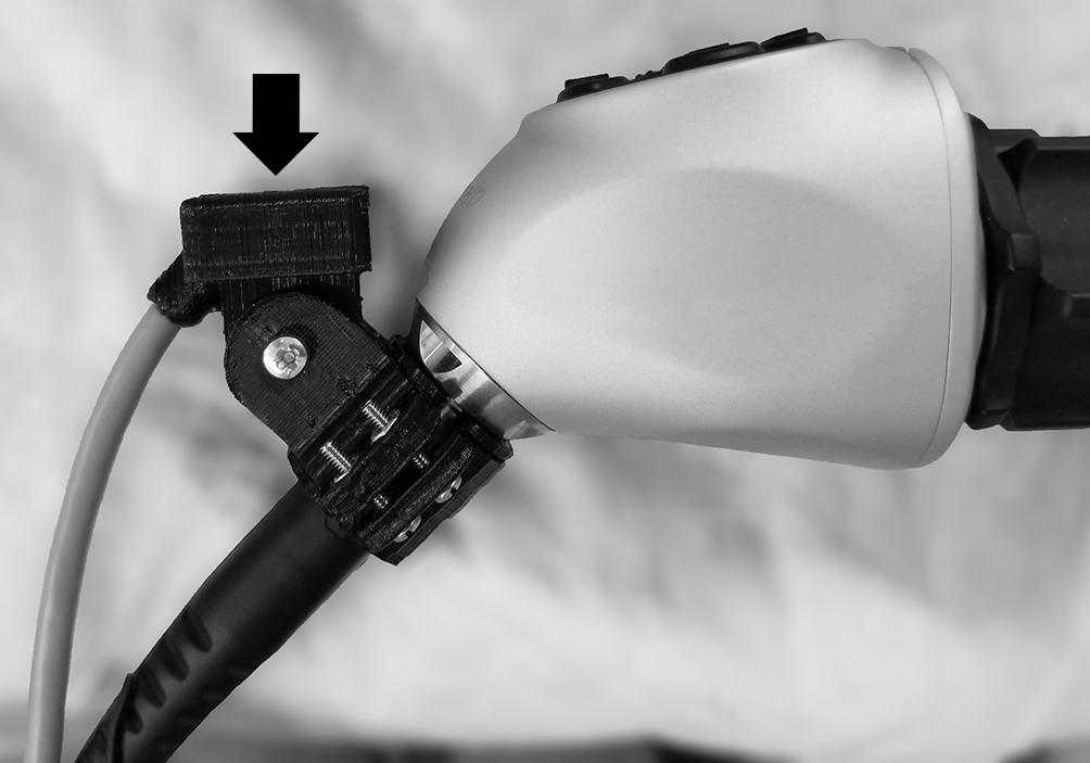
Figure 1: Inertial sensor (black arrow) attached to a conventional arthroscopic camera by means of an universal holder. This is secured with a conventional screwdriver.
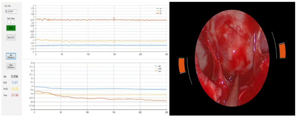
Figure 2: On the left, tridimensional information provided by the sensor, shown in the computer screen. On the right, translation and input of that information onto the arthroscopic screen, in the form of two semicircular bars that change in size and color according to the camera angulation.
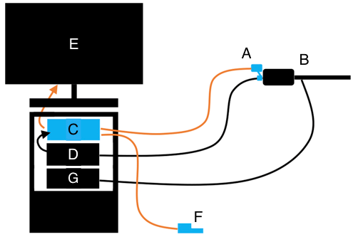
Figure 3: System construct. The sensor (A) is attached to the arthroscopic camera (B). A conventional computer or laptop (C) receives the information provided from the sensor (A) and the camera console (D). A monitor (E) shows the final image. The system is operated by means of a foot pedal (F). G: light source.
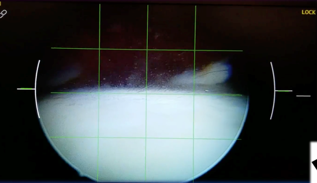
Figure 4: Screenshot showing a 4×4 grid which allows for a neutral plane to be set.
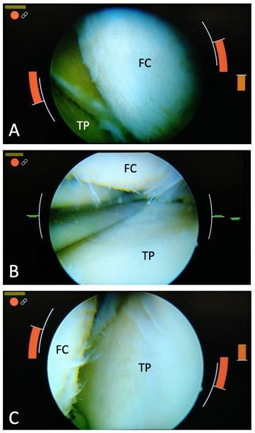
Figure 5: Example of system functioning. Image B shows a horizontal correctly oriented working plane in the medial compartment, between the Femoral Condyle (FC) and the tibial plateau (TP). Note there are no color marks on the sides (= neutral plane) .In the upper image A, the camera has been excessively rotated to the right; the red marks in both sides of the image warn about this distortion. In image C, the excessive rotation occurs to the left side, while red warning bars appear in the opposite direction.
Test During Knee Arthroscopy
A pilot experience was designed to explore the applicability of the system during knee arthroscopic procedures. Patients were selected from the main author waiting list, and provided written consent to participate. The procedures were performed in the surgical area of San Roque Meloneras Hospital, Gran Canaria, after obtaining the preceptive permissions, including local ethics committee approval. Viera-Artiles was present during the session to assist with the technical elements.
The test consisted in performing 2 regular knee arthroscopies as per SB routine, indicated for degenerative meniscal tears. Spinal blocks were applied and patients were positioned in supine position, with legs resting in free flexion. A leg holder and tight tourniquet were applied. Routine skin preparation and leg draping followed. The sensor was attached to the camera before covering the construct with an sterile cover, along with the output wiring, as per the SB common proceeding.
The surgical procedure was performed in a routine fashion. Anterolateral and anteromedial portals were utilized, and joint inspection was performed. Once the diagnose of degenerative medial meniscal tears was confirmed, partial medial meniscectomies were performed with arthroscopic punches and motorized shaver. The system was tested during various phases of the procedures; no additional manoeuvres or surgical steps were performed.
Results
Both interventions were completed without unexpected complications. The operation theatre was set up in the usual fashion for a routine knee arthroscopy. Prior to the first intervention, system setting took approximately 15 minutes of additional time. No additional instruments or items were needed during the experience.
The addition of the inertial sensor did not make a significant difference in the camera grip, ease of manipulation or weight, as the sensor only adds 26 grams to the construct. The image quality provided by the system did not differ from the regularly obtained with the arthroscopic camera. There was no appreciable lag between image acquisition and screen display.
During knee inspection, the system “0-degree reference” has to be determined for every working field. This is easily performed by the surgeon with a foot pedal, or by means of an assistant directly from the computer; in both cases the level is set instantly with a single button push.
We encountered that the system provides a clear orientation assistance mainly in two scenarios:
- Exploration and intervention in the retro and supra patellar space with extended knee. As the movements in this field are mostly biplanar (medio-lateral x proximal-distal), the definition of a reference working plane is easily achievable (Fig. 4). A practical application of the device would be positioning assistance during liberation of the suprapatellar pouch in cases of arthrofibrosis-scarring, where even experienced surgeons may disorientate due to the lack of anatomic referencing
- Exploration and manipulation of menisci. Using the medial and lateral tibial plateau as references, a proper working plane can be chosen for the medial and lateral compartments, respectively (Fig. 5). This can assist with adequate camera orientation during meniscectomies, especially when different arthroscopic instruments are required, as novel surgeons tend to involuntarily change the camera focus while shifting tools
Apart from the time initially spent for system adjustments, the total surgical time for both procedures was comparable to routine meniscectomies (30 and 27 minutes respectively).
Discussion
There was a time when joint arthroscopy was relegated for training and upcoming orthopaedic surgeons; not every senior consultant was interested in performing arthroscopic procedures. However, in the last two decades, arthroscopic procedures have topped the list of most frequently performed procedures among American Orthopaedic Boards applicants [1]. Current orthopaedic surgeons must achieve at least a basic level of arthroscopic skills for their day-to-day practice; an illustrative example is the fact that it may be hard to justify an open arthrotomy to wash and a debride an acute knee septic arthritis in a setting with arthroscopy availability. In addition, the variety of procedures performed arthroscopically has been growing exponentially, for most joints and conditions. Therefore, arthroscopic training is no longer conceived as an optional or supplementary surgical skill.
To date, the first steps in AT are generally performed in conventional or virtual simulators, artificial models or cadaveric specimens [4-6]. Cadaveric training has shown effectiveness, even in not technically simple procedures such as Bankart lesion repairs in the shoulder [7]. However, virtual simulators and cadaveric specimens are expensive, and generally not accessible in every centre with learning surgeons, who have to travel elsewhere to put their hands on them. Therefore, there is a need to increase the efficiency of AT, with a specific goal on reducing learning curve times.
Not until some mastery has been achieved, real surgeries in patients are performed. Some surgeons may find this leap too aggressive, and long for further assistance while performing real cases. Some authors have highlighted that current clinical pressure may be limiting the availability of senior surgeons for involving themselves in teaching of their younger counterparts [8]. Therefore, there has been an interest in providing real-time assistance to support orientation and camera positioning during actual operating for unexperienced arthroscopists.
Operating the arthroscopic camera requires certain skills that have to be trained. A crucial one is being able to maintain a stable horizon while performing tasks with the surgical instruments; inadvertent camera roll might lead to disorientation and compromise the safety and accuracy of procedures. The system created by Viera-Artiles, et al., which is inexpensive and adjustable to every surgical camera, could overcome this limitation, inherent to the technique. Head and neck trainees were able to perform varied surgical gestures with higher accuracy when the gyroscopic sensor was attached to the camera [3]. During our experience in knees, it was noted that the system provided immediate visual warning when the camera tilted excessively in relation to the operational plane. We interpret this as an invaluable aid for novel arthroscopists, as incorrect camera positioning can be automatically corrected in the very moment this is happening. The principle of this is similar to the bicycle stabilizers for kids: each time an excessive tilt occurs, the stabilizers (visual alerts) will act, helping to recover the correct positioning. We also believe this system has a potential to be used in other specialities with endoscopic procedures, such as chest surgery, abdominal procedures, urology or gynaecology.
Varied approaches to update AT methods have been published. Making the most of decades of experience with joint navigation in prosthetic surgery, some authors have recently applied navigation principles to improve orientation during arthroscopy. A Japanese group tested its applicability in resin models for elbow arthroscopy, with favourable results [9]. Jung, et al., tested navigation in phantoms and cadaveric models of the shoulder, while performing anchor insertions and testing the placement accuracy [10]. A recent review highlighted the efficacy of navigation in assisting arthroscopy of the hip, often labelled as the most challenging joint to approach [11]. However, this interesting methodology adds significant costs (navigation system and trackers) to the procedure.
Following a different principle, several authors have provided real-time assisting information during arthroscopic surgery by means of genuine contributions. Lee, et al., published a device similar to Viera-Artiles´, testing its utility in an artificial airway model [12]. Ma, et al., presented a system based on virtual or augmented reality to assist with camera positioning and orientation during knee arthroscopy [13]. In this prototype, real time images are combined with preoperative imaging (CT or MRI), and during surgery, a virtual 3D overview of the working field is displayed. We find this creation potentially useful, providing extensive multiplanar information, but has yet to be tested in real surgeries. Moreover, the need for image pre-processing may limit its applicability. A similar work on augmented reality was published by Chen, et al., also tested in mock and swine joints with promising results [14].
Limitations
The main limitation of this study is its design as a preliminary experience. Further efforts involving larger numbers of procedures are likely needed to assume more robust conclusions. In addition, testing the system on surgeons with different level of expertise would also be desirable.
Conclusion
We believe this inertial sensor-based system may contribute significantly to AT, especially aiding novel surgeons to improve intraoperative orientation at different stages of their training, and more importantly, when real cases are being performed. In addition, more experienced surgeons might find this device useful in specific settings where the anatomical landmarks are not completely visible, such as in extensive scarring or with the presence of bloody or turbid fluid. The low cost of the device, scarce equipment required and universal applicability to pre-existing camera models guarantee a vast accessibility to most healthcare settings. Furthermore, the device can be applied in a variety of surgical specialities, reassuring the cost-benefit of incorporating it to centres with varied medical training. Nevertheless, further studies should be performed to quantify the specific gains obtained with the use of this device.
Conflict of Interest
The authors of this manuscript declare no compelling conflicts of interest.
Ethical Approval
Ethical approval was granted by the local committee, with the reference number: CEIm HUGCDN: 2021-303-1
References
- Garrett Jr WE, Swiontkowski MF, Weinstein JN, Callaghan J, Rosier RN, Berry DJ, et al. American Board of Orthopaedic Surgery Practice of the Orthopaedic Surgeon: part-II, certification examination case mix. JBJS. 2006;88(3):660-7.
- Conrad J, Shah AH, Divino CM, Schluender S, Gurland B, Shlasko E, Szold A. The role of mental rotation and memory scanning on the performance of laparoscopic skills. Surg Endo Interventional Techniq. 2006;20(3):504-10.
- Viera Artiles J, Valdiande Gutiérrez JJ, Ospina Díaz JA, Costales Marcos M, López Higuera JM. An inertial sensor-based system designed to measure and prevent undesired camera rotation during endoscopic sinus surgery. Int Forum Allergy and Rhinol. 2020;10:689-91.
- Çetinkaya E, Çift H, Aybar A, Erçin E, Güler GB, Poyanlı O. The timing and importance of motor skills course in knee arthroscopy training. Acta Orthopaedica Et Traumatologica Turcica. 2017;51(4):273-7.
- Bouaicha S, Jentzsch T, Scheurer F, Rahm S. Validation of an arthroscopic training device. Arthroscopy: J Arthro Relt Surg. 2017;33(3):651-8.
- Stunt JJ, Kerkhoffs GM, Horeman T, van Dijk CN, Tuijthof GJ. Validation of the passport V2 training environment for arthroscopic skills. Knee Surgery, Sports Traumatology, Arthro. 2016;24(6):2038-45.
- Angelo RL, St Pierre P, Tauro J, Gallagher AG, Barber A, Beach W, et al. A proficiency-based progression simulation training curriculum to acquire the skills needed in performing arthroscopic Bankart and rotator cuff repairs-implementation and impact. Arthroscopy: J Arthrosco Rel Surg. 2021;37(4):1099-106.
- Stirling ER, Lewis TL, Ferran NA. Surgical skills simulation in trauma and orthopaedic training. J Ortho Surg Res. 2014;9(1):1-9.
- Shigi A, Oka K, Tanaka H, Abe S, Miyamura S, Takao M, et al. Validation of the registration accuracy of navigation-assisted arthroscopic débridement for elbow osteoarthritis. J Shoulder Elbow Surg. 2019;28(12):2400-8.
- Jung K, Kim H, Kholinne E, Park D, Choi H, Lee S, et al. Navigation-assisted anchor insertion in shoulder arthroscopy: a validity study. BMC Musculoskeletal Disorders. 2020;21(1):1-9.
- Stražar K. Computer assistance in hip preservation surgery-current status and introduction of our system. Int Orthopaedics. 2021;45(4):897-905.
- Lee HC, Jung CW, Kim HC. Real-time endoscopic image orientation correction system using an accelerometer and gyrosensor. PlosOne. 2017;12(11):e0186691.
- Ma C, Cui X, Chen F, Ma L, Xin S, Liao H. Knee arthroscopic navigation using virtual-vision rendering and self-positioning technology. Int J Computer Assisted Radiol Surg. 2020;15(3):467-77.
- Chen F, Cui X, Han B, Liu J, Zhang X, Liao H. Augmented reality navigation for minimally invasive knee surgery using enhanced arthroscopy. Computer Methods and Programs in Biomed. 2021;201:105952.
Article Type
Original Article
Publication History
Received Date: 12-10-2021
Accepted Date: 06-11-2021
Published Date: 13-11-2021
Copyright© 2021 by Sergio BR, et al. All rights reserved. This is an open access article distributed under the terms of the Creative Commons Attribution License, which permits unrestricted use, distribution, and reproduction in any medium, provided the original author and source are credited.
Citation: Sergio BR, et al. A Novel Device to Prevent Undesired Arthroscopic Camera Rotation. J Ortho Sci Res. 2021;2(3):1-11.

Figure 1: Inertial sensor (black arrow) attached to a conventional arthroscopic camera by means of an universal holder. This is secured with a conventional screwdriver.

Figure 2: On the left, tridimensional information provided by the sensor, shown in the computer screen. On the right, translation and input of that information onto the arthroscopic screen, in the form of two semicircular bars that change in size and color according to the camera angulation.

Figure 3: System construct. The sensor (A) is attached to the arthroscopic camera (B). A conventional computer or laptop (C) receives the information provided from the sensor (A) and the camera console (D). A monitor (E) shows the final image. The system is operated by means of a foot pedal (F). G: light source.

Figure 4: Screenshot showing a 4×4 grid which allows for a neutral plane to be set.

Figure 5: Example of system functioning. Image B shows a horizontal correctly oriented working plane in the medial compartment, between the Femoral Condyle (FC) and the tibial plateau (TP). Note there are no color marks on the sides (= neutral plane) .In the upper image A, the camera has been excessively rotated to the right; the red marks in both sides of the image warn about this distortion. In image C, the excessive rotation occurs to the left side, while red warning bars appear in the opposite direction.
